Vision Tool
Vision Tool is the screen for configuring and managing the vision objects used in machine-vision inspection. You reach it through the Vision Tool setup, and it defines cameras, images, and inspection tools in one place to build a vision-inspection configuration.
Note: The Vision Tool Editor is currently under active development, and some features may not be available yet.
The screen consists of list sections by kind on the left and an editing form on the right. Selecting a camera or tool on the left brings up the configuration form for that kind on the right, and you work by entering values in the form to add, modify, and delete items.
Left — list sections
On the left, four card sections that divide vision objects by kind are stacked vertically. Selecting an item in a section's list switches the right-hand editing form to that kind.
| Section | Target |
|---|---|
CAMERA | The camera that acquires images. |
IMAGE | The image used for inspection. |
VISION SYSTEM TOOL | A system-scoped vision-inspection tool. |
VISION JOBFILE TOOL | A vision-inspection tool based on a job file. |
Right — editing form
On the right, one of the camera, image, or vision-tool configuration forms is shown according to the kind selected on the left. Each form has Add, Set, and Delete buttons at the bottom to add an item with the entered values, apply them to the selected item, and delete an item.
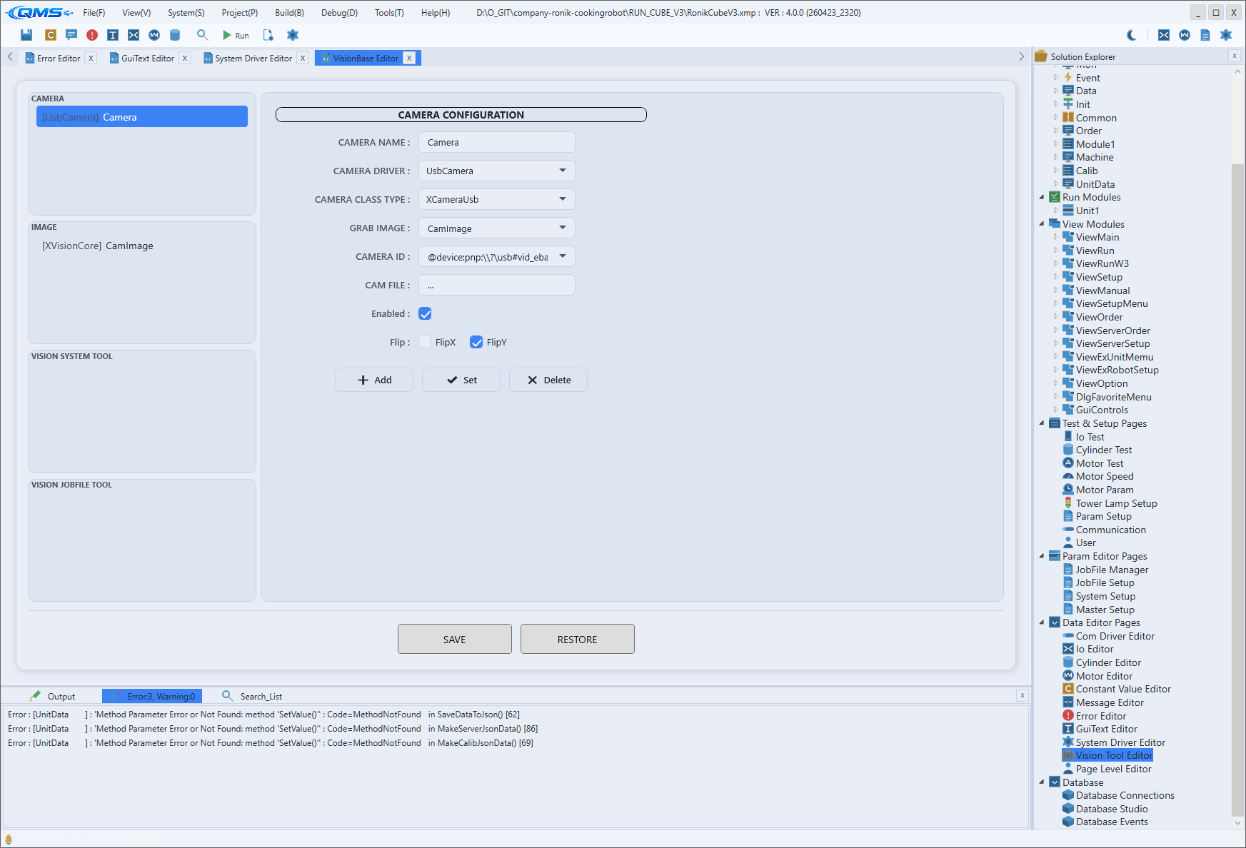
CAMERA CONFIGURATION
The form that defines a camera. Specify the camera name and driver, the image-acquisition target, and the connection information.
| Field | Content |
|---|---|
CAMERA NAME | Camera name. |
CAMERA DRIVER | Camera driver to use. |
CAMERA CLASS TYPE | Camera class kind. |
GRAB IMAGE | Name of the image to receive the captured frame. |
CAMERA ID | Camera identifier (for example, an IP address). |
CAM FILE | Camera configuration file. |
Enabled | Whether the camera is used. |
Flip | Horizontal (FlipX) and vertical (FlipY) flip of the image. |
IMAGE CONFIGURATION
The form that defines an image for inspection; specify IMAGE NAME, IMAGE DRIVER, and IMAGE CLASS TYPE. It manages the frame acquired from a camera as a named image so that tools can reference it.
VISION TOOL CONFIGURATION
The form that defines a vision-inspection tool. Specify the tool name and driver, the inspection type, and the image the tool will inspect.
| Field | Content |
|---|---|
TOOL NAME | Tool name. |
TOOL DRIVER | Tool driver. |
VISION TOOL TYPE | Inspection type (for example, Find). |
VISION TOOL CLASS TYPE | Tool class kind. |
TOOL LINK IMAGE | The target image the tool will inspect. |
Saving
The SAVE button at the bottom of the screen saves the edited vision-object configuration, and the RESTORE button reverts to the last saved state. After arranging items with per-form Add, Set, and Delete, commit the whole configuration with SAVE.
Driver and screen links
The camera and tool drivers specified here use the drivers registered as the Cameras and VisionTools items of the Project Driver and System Driver. In other words, the drivers themselves are registered on the driver screens, and on this screen you configure the inspection tools that use those drivers.
Inspection results are output to the vision-display controls on the operation screen. For how to place vision results on the screen, see the View Module.
Workflow
- Select the section for the kind to configure (camera, image, or tool) on the left.
- Enter the necessary values, such as name and driver, in the form on the right.
- Add a new item with
Add, or pick an existing item and apply withSet. - Link the tool to its target image with
TOOL LINK IMAGEin the tool form. - When the configuration is complete, save with
SAVE.