Communication Driver Editor
Communication Driver Editor is the editor for defining the serial and network communication drivers used to exchange data with external devices. The screen title is COMMUNICATION DRIVER EDITOR, and for each communication channel you register a name, driver type, and port parameters. The entry path is by way of the System Driver / Project Driver screens or from the communication settings; the communications defined here are used from scripts in Communication and verified on the 24-communication test screen.
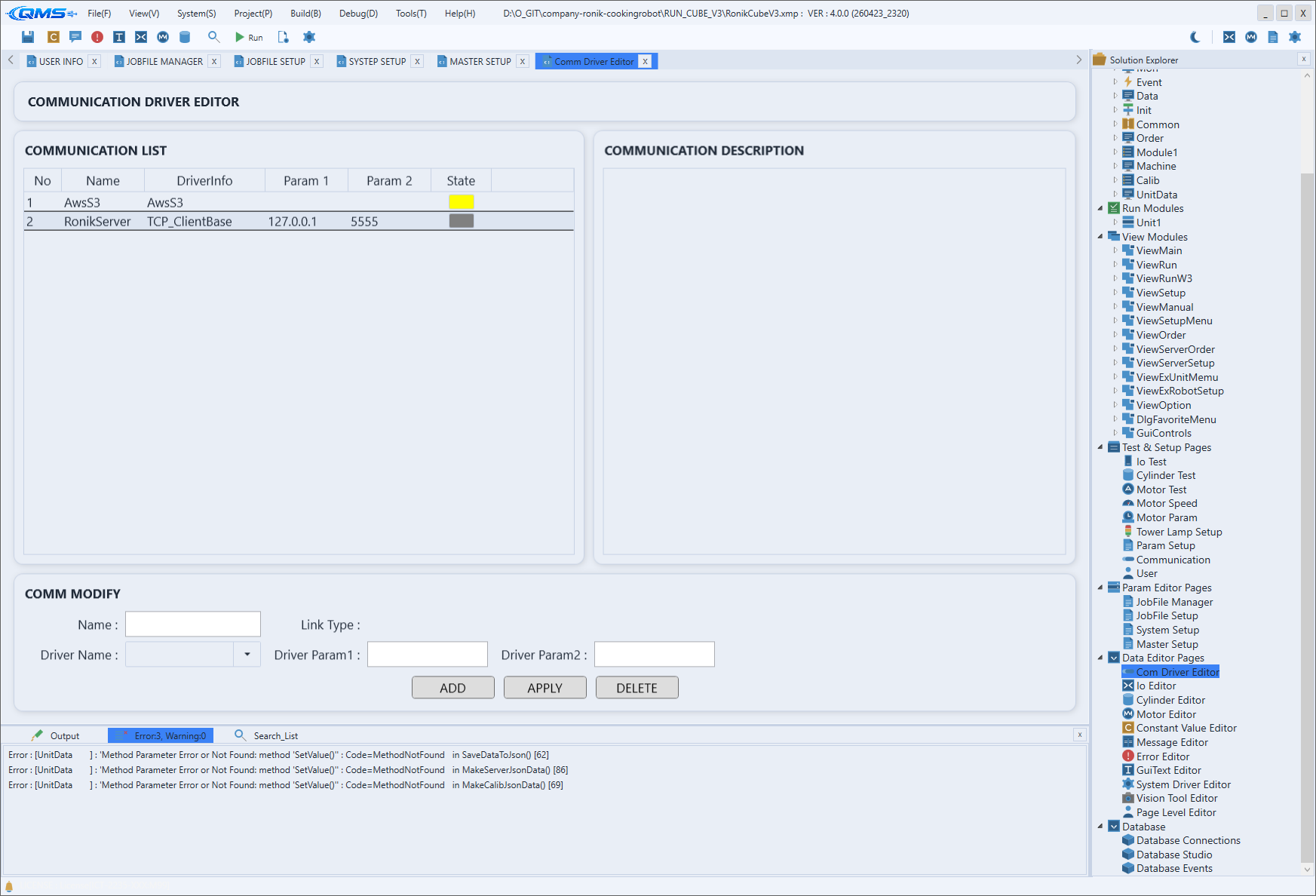
The screen consists of a communication list on the left, a description box on the right, and an editing area at the bottom. Selecting a channel in the list shows that driver's description on the right, and you edit the values in the bottom editing area.
Main areas
The screen is divided into three card-shaped areas. The label and role of each area are as follows.
| Area | Description |
|---|---|
| COMMUNICATION LIST | Left-hand DataGrid. Shows the defined communication channels, one per row. |
| COMMUNICATION DESCRIPTION | Right-hand read-only box. Shows the driver description of the selected channel. |
| COMM MODIFY | Bottom editing area. Enter and apply the name, driver, and parameters of the selected channel. |
COMMUNICATION LIST columns
Each row in the left-hand list is a single communication channel. The column layout is as follows.
| Column | Description |
|---|---|
No | The channel sequence number. |
Name | The communication channel name. Referenced by this name from scripts. |
DriverInfo | The driver (class) type connected to the channel. |
Param 1 · Param 2 | The port/protocol parameters passed to the driver. |
State | Indicates the channel's connection state with a colored indicator. |
COMM MODIFY fields
In the bottom editing area you edit the values of the selected channel or add a new channel. The input fields and buttons are as follows.
| Field · Button | Description |
|---|---|
Name | Enter the communication channel name. |
Link Type | Shows the connection method of the selected driver (serial, network, etc.). |
Driver Name | A combo box for selecting the driver to use. |
Driver Param1 · Driver Param2 | Enter the parameters passed to the driver. Their meaning depends on the driver type. |
ADD | Adds a new communication channel with the entered values. |
APPLY | Applies the changes to the selected channel. |
DELETE | Deletes the selected channel. |
Because the meaning of the Driver Param1 and Driver Param2 labels changes with the selected driver, it
is safest to choose the driver first and then enter the parameters.
Workflow
- Open Communication Driver Editor from System Driver / Project Driver or from the communication settings.
- To create a new channel, enter
NameinCOMM MODIFYand select a driver withDriver Name. - Enter the port/protocol parameters in
Driver Param1andDriver Param2. - Add the channel with
ADD, or select an existing channel, edit its values, and apply withAPPLY. - Check the connection state with the
Statecolor inCOMMUNICATION LIST, and verify the communication on the 24-communication screen.